The goal of cycle analysis is to estimate operation parameters of the propellant feed system which meets required design parameters, such as:
- Thrust chamber pressure
- Propellant components mass flow rate
- Propellant components mixture ratio
Table of contents
Cycle Analysis
When configured properly, the program obtains the following operation parameters of the propellant feed system:
- Operational parameters of combustion devices (gas generators or preburners): pressure, mass flow rate and mixture ratio
- Operational parameters of each of turbopump components: mass flow rate, inlet pressure, discharge pressure, shaft power
- Overall performance of the rocket engine (usually estimated only for gas generator and tap-off cycles)
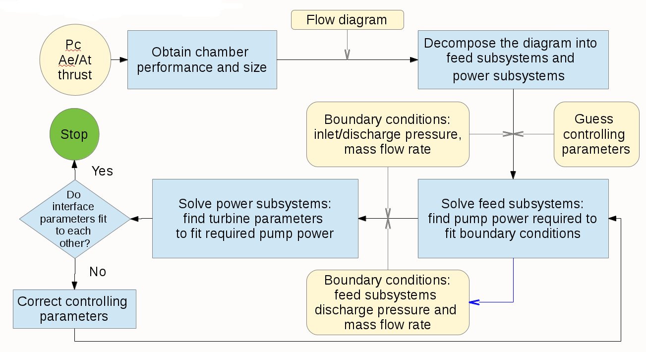
The diagram below presents the typical cycle analysis flowchart (click the image to enlarge it):
Input data
The following input data has to be available before starting the preparation of design parameters for cycle analysis:
- Design parameters required for performance analysis and thrust chamber sizing
- Physical properties of propellant components
- Engine cycle type
- Propellant feed system flow schematic
- Parameters of elements in propellant feed system
- Parameters of propellant components at engine inlet
Prerequisites: performance analysis and thrust chamber sizing
Cycle analysis module utilizes the results of performance analysis and thrust chamber sizing, therefore the user has to provide all design parameters required for performance analysis and thrust chamber sizing.
Because the cycle analysis depends on results of performance analysis and thrust chamber sizing, it can be performed only if the mentioned two modules were succesfully executed.
Physical properties of propellant components
Similar to thermal analysis, cycle analysis can only be used with propellant components which were properly defined either in standard data library file
<RPA installation directory>/resources/properties.inp or in user data library
<user.application.data>/resources/usr_properties.inp.
The proper component definition includes such parameters as density, viscosity, thermal conductivity, and heat of evaporation. These parameters may be defined either for normal conditions or for the range of conditions (pressure, temperature).
Standard data library delivered in RPA distribution package includes following components with defined physical properties:
| Component | Ranges |
|---|---|
| LH2 | p=(0.1...60) MPa, T=(20...600) K |
| LOX | p=(0.1...60) MPa, T=(63...973) K |
| C2H5OH(L) | p=(0.1...30) MPa, T=(253...593) K |
| CH4(L) | p=(0.1...60) MPa, T=(100...600) K |
| C3H8(L) | p=(0.1...49) MPa, T=(140...590) K |
| CH6N2(L) | p=0.1 MPa, T=(223...323) K |
| C2H8N2(L),UDMH | p=0.1 MPa, T=(203...333) K |
| N2H4(L) | p=0.1 MPa, T=(289...387) K |
| N2O4(L) | p=0.1 MPa, T=(263...343) K |
| RP-1 | p=0.1 MPa, T=(289...422) K |
| T-1 | p=0.1 MPa, T=(273...298) K |
Physical properties of component at conditions within defined ranges are calculated using one of interpolation methods. Component properties at conditions below or above defined ranges are taken at nearest point in the available range.
User may specify properties for further components, defining them in user data library file. To make it easier, RPA provides embedded thermodynamic database editor.
Type of engine cycle and its top-level parameters
RPA Standard v.2 supports following cycle types:
- gas generator cycle (GG)
- staged combustion cycle (SC)
- full-flow staged combustion cycle (FFSC)
All cycles allow variations of the flow diagram including the number of combustion devices (gas generator or preburner), the number of turbopumps, arrangement of turbines (serial or parallel), availability of booster pumps, availability of kick pumps, availability of tap-off branches.
Top-level parameters include:
- Type of combustion devices:
- oxidizer-rich
- fuel-rich
- Number of independent turbopumps
- Number of gas generators/preburners
GG cycle typically utilizes a fuel-rich combustion device (gas generator), because combustion products generated in such device usually have better energetics and lower chemical activity which allows higher temperature, which in turn provides yet more drive power.
SG cycle may utilize both fuel-rich and oxidizer-rich combustion devices (preburners). The selection depends on concrete type of propellant: engines operating on liquid hydrogen are designed with fuel-rich preburner, whereas engines operating on hydrocarbon fuels are usually designed with oxidizer-rich preburner.
Because of its design, FFSC cycle utilizes both types at once.
Propellant feed system flow diagram
Propellant feed system flow diagram has to be defined.
For example, the following flow diagram represents the SC cycle with oxidizer-rich prebirner (click the image to enlarge it):
| Flow schematic |
|---|
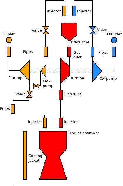 |
Parameters of elements in propellant feed system
The current version of the program is capable of obtaining the operational parameters of the whole feed system, but parameters of many of its subcomponents have to be specified by the user.
User has to provides following parameters:
- Efficiency of pumps and turbines
- Pressure drop in valves, injectors, cooling jackets
The following table provides information on how to define required parameters:
| Subcomponent | Parameter | Typical Values | Comments |
|---|---|---|---|
| Combustion device | Pressure |
|
For GG cycle the gas generator pressure is an input parameter. For SC and FFSC cycles the preburner pressure is obtained by RPA as a result of analysis. |
| Pressure drop coefficient | 0.9...0.95 | The value defines the pressure drop between injector of the combustion device and turbine inlet. | |
| Temperature |
|
The temperature in combustion device is limited by corrosion- and heat-resistance as well as high-temperature strength of used construction materials. | |
| Turbine | Pressure ratio | 10...20 | Required for GG cycle only. Obtained by RPA for SC and FFSC cycles. |
| Efficiency | 0.5...0.8 | ||
| Arrangement | Serial or parallel flow | Required for second turbine in configurations with one combustion device | |
| Main pump | Efficiency | 0.6...0.8 | For single-shaft turbopumps typical values are: 0.7-0.8 for oxidizer pump 0.55-0.7 for fuel pump. |
| Booster pump | Efficiency | 0.5...0.7 | Optional parameter if booster pump is available |
| Discharge pressure | (1.5...2)pinlet | Optional parameter if booster pump is available | |
| Booster pump drive | Type |
|
Optional parameter if booster pump is available |
| Turbine pressure ratio |
|
Optional parameter if booster pump with dedicated turbine is available | |
| Turbine efficiency | 0.5...0.7 | Optional parameter if booster pump with dedicated turbine is available | |
| Valve | Pressure drop | (0.1...0.2)pc | Main feed branch |
| (0.1...0.15)pc | Combustion device feed branch | ||
| Cooling jacket | Pressure drop | (0.25...0.35)pc | |
| Injector | Pressure drop |
(0.4...0.8)(pc)0.5 or (0.3...1.5) MPa |
|
| Kick pump | Efficiency | 0.3...0.5 | If no kick pump is defined, the pump of the main branch has to produces such a discharge pressure that it fits to inlet of gas generator/preburner. Usually no kick pump is required for gas generator cycle, whereas an absence of kick pump in staged combustion cycle leads to significant pressure raise. |
| Secondary feed branch | Inlet relative cross-section area | 0.1...0.3 | Defines the inlet cross-section area of the branch relative to the inlet cross-section area the main branch. |
Parameters of propellant components at engine inlet
Inlet parameters of component such as pressure and velocity have to be selected:
| Parameter | Typical Values | Comments |
|---|---|---|
| Inlet pressure of component | (0.3...0.8) MPa | Inlet pressure of component is defined by conditions in the component tank. |
| Inlet velocity of component |
|
Inlet velocity of component is mainly defined by mass flow rate and cross-section area of the inlet. In order to reduce the hydraulic losses, inlet velocity is usually selected from the specified range. |
Propellant feed system decomposition
The modelling of the engine cycle with RPA requires the decomposition of the the feed system into 3 subsystems:
- Fuel feed subsystem
- Oxidizer feed subsystem
- Power subsystem
Component (fuel or oxidizer) feed subsystem begins at component inlet of the fuel and ends at injectors of combustion chamber and/or combustion device (GG or preburner). It includes booster, main and kick pumps, valves, cooling jackets, injectors, and sub-branches.
Power subsystem begins at combustion device (GG or preburner) and ends either at injector of thrust chamber (in SC and FFSC cycles) or at exhaust nozzle (in GG cycle). It includes combustion device, gas ducts, turbine, injector (in SC and FFSC cycles) and nozzle (in GG cycle).
| Flow schematic | Fuel feed subsystem |
Oxidizer feed subsystem |
Power subsystem |
|
|---|---|---|---|---|
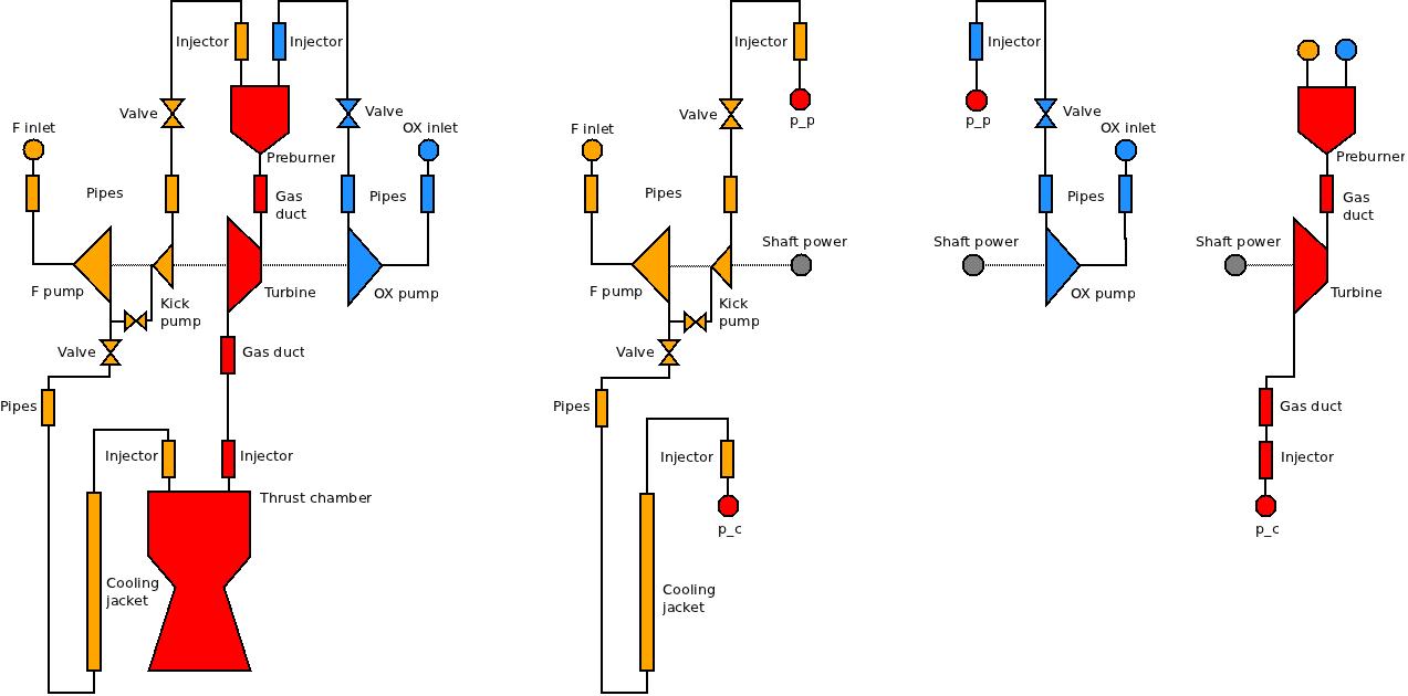 |
|
|
|
|
| Comments: |
The subsystem consists of:
|
The subsystem consists of main branch only. | ||
| How RPA solves the subsystem problems: | Find such pump power that the required pressure is achieved at exit port of each branch (p_c and/or p_p). | Find such parameters of combustion device and/or turbine that produced power is equal to required total pump power of the feed subsystem. | ||
Example
To demonstrate the selection and definition of input data, an example problem has been prepared using the flow diagram specified above.
Input data:
| Subsystem | Parameter | Value |
|---|---|---|
| Engine | Nominal thrust | 200 kN at sea level |
| Number of thrust chambers | 1 | |
| Thrust chamber | Pressure | 20 MPa |
| Propellant components |
|
|
| Nozzle cobditions |
|
|
| Sizing design parameters |
|
|
| Engine | Cycle type | Staged combustion |
| Top-level cycle parameters |
|
|
| Power subsystem | Pressure drop coefficient | 0.9 |
| Temperature in preburner | 770 K | |
| Turbine efficiency | 0.79 | |
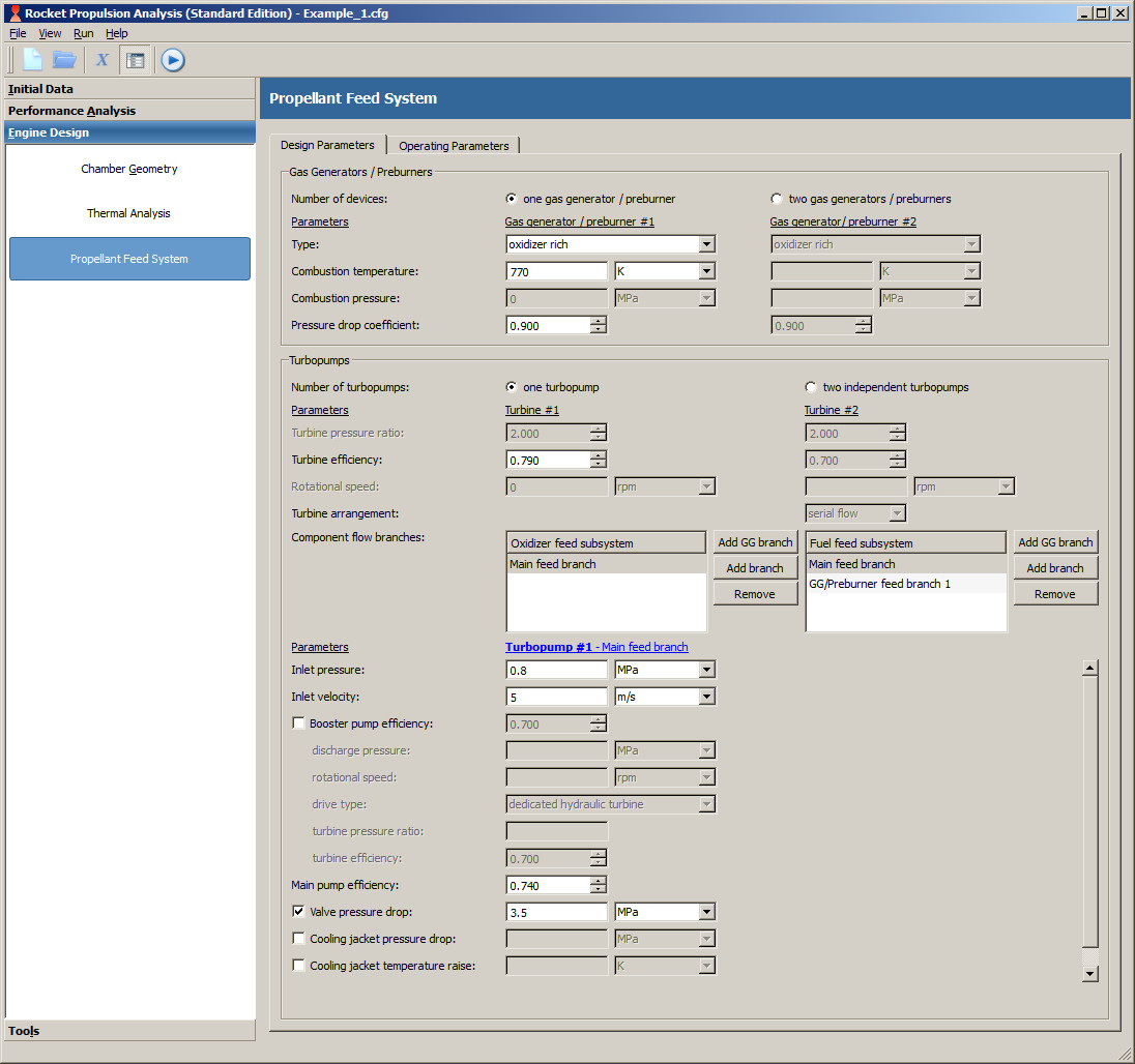
| Oxidizer feed subsystem (main feed branch) | Inlet pressure | 0.8 MPa |
| Inlet velocity | 5 m/s | |
| Main pump efficiency | 0.74 | |
| Valve pressure drop | 3.5 MPa | |
| Injector pressure drop | 2.0 MPa | |
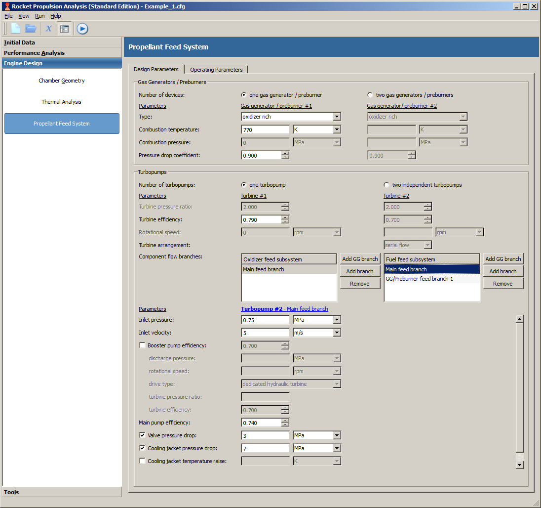
| Fuel feed subsystem (main feed branch) | Inlet pressure | 0.75 MPa |
| Inlet velocity | 5 m/s | |
| Main pump efficiency | 0.74 | |
| Valve pressure drop | 3.0 MPa | |
| Cooling jacket pressure drop | 7.0 MPa | |
| Injector pressure drop | 2.0 MPa | |
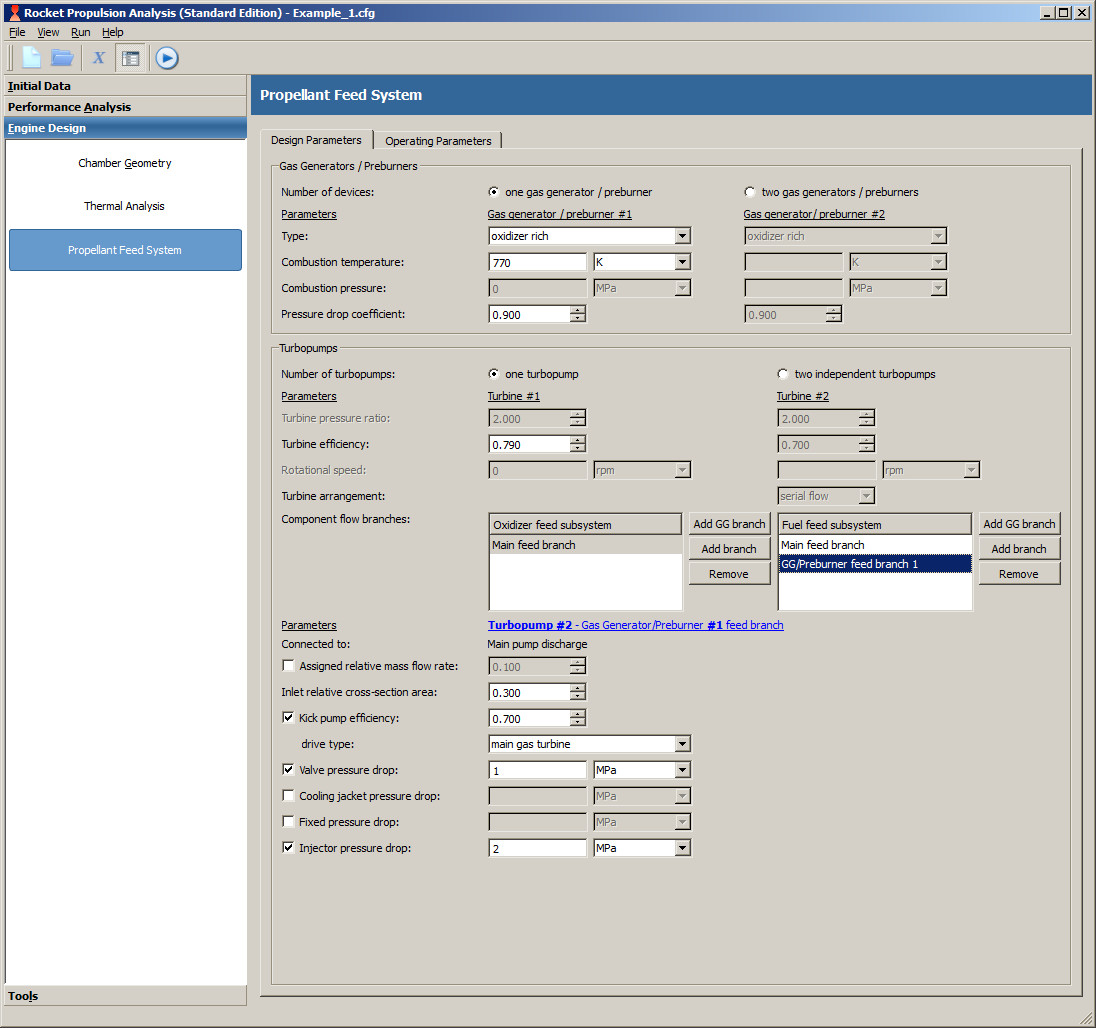
| Fuel feed subsystem (preburner feed branch) | Inlet relative cross-section area | 0.30 |
| Kick pump efficiency | 0.70 | |
| Kick pump drive type | main gas turbine | |
| Valve pressure drop | 1.0 MPa | |
| Injector pressure drop | 2.0 MPa |
Download prepared configuration file: Example_1.cfg
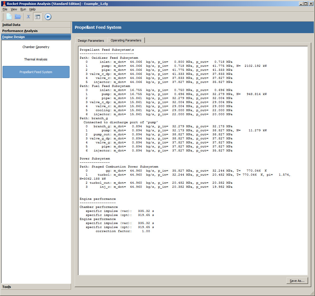
Estimated operation parameters of the propellant feed system 1:
Propellant Feed Subsystem\s
---------------------------
Path: Oxidizer Feed Subsystem
   0      inlet: m_dot=  44.066  kg/s, p_in=   0.800 MPa, p_out=   0.718 MPa
   1       pump: m_dot=  44.066  kg/s, p_in=   0.718 MPa, p_out=  41.775 MPa, N=  2102.192 kW
   2       pipe: m_dot=  44.066  kg/s, p_in=  41.775 MPa, p_out=  41.333 MPa
   3 valve_c_dp: m_dot=  44.066  kg/s, p_in=  41.333 MPa, p_out=  37.833 MPa
   4    valve_c: m_dot=  44.066  kg/s, p_in=  37.833 MPa, p_out=  37.827 MPa
   5   injector: m_dot=  44.066  kg/s, p_in=  37.827 MPa, p_out=  35.827 MPa
Path: Fuel Feed Subsystem
   0      inlet: m_dot=  16.755  kg/s, p_in=   0.750 MPa, p_out=   0.696 MPa
   1       pump: m_dot=  16.755  kg/s, p_in=   0.696 MPa, p_out=  32.279 MPa, N=   948.814 kW
   2       pipe: m_dot=  15.861  kg/s, p_in=  32.279 MPa, p_out=  32.004 MPa
   3 valve_c_dp: m_dot=  15.861  kg/s, p_in=  32.004 MPa, p_out=  29.004 MPa
   4    valve_c: m_dot=  15.861  kg/s, p_in=  29.004 MPa, p_out=  29.000 MPa
   5    cooling: m_dot=  15.861  kg/s, p_in=  29.000 MPa, p_out=  22.000 MPa
   6   injector: m_dot=  15.861  kg/s, p_in=  22.000 MPa, p_out=  20.000 MPa
Path: branch_g
  Connected to discharge port of 'pump'
   0   branch_g: m_dot=   0.894  kg/s, p_in=  32.279 MPa, p_out=  32.173 MPa
   1       pump: m_dot=   0.894  kg/s, p_in=  32.173 MPa, p_out=  38.827 MPa, N=    11.279 kW
   2   pump_out: m_dot=   0.894  kg/s, p_in=  38.827 MPa, p_out=  38.827 MPa
   3 valve_g_dp: m_dot=   0.894  kg/s, p_in=  38.827 MPa, p_out=  37.827 MPa
   4    valve_g: m_dot=   0.894  kg/s, p_in=  37.827 MPa, p_out=  37.827 MPa
   5       pipe: m_dot=   0.894  kg/s, p_in=  37.827 MPa, p_out=  37.827 MPa
   6   injector: m_dot=   0.894  kg/s, p_in=  37.827 MPa, p_out=  35.827 MPa

Power Subsystem
---------------
Path: Staged Combustion Power Subsystem
   0         gg: m_dot=  44.960  kg/s, p_in=  35.827 MPa, p_out=  32.244 MPa, T= 770.046  K
   1     turbo1: m_dot=  44.960  kg/s, p_in=  32.244 MPa, p_out=  20.482 MPa, T= 770.046  K,
                 pi=      1.574,       N=   3062.188 kW
   2 turbo1_out: m_dot=  44.960  kg/s, p_in=  20.482 MPa, p_out=  20.382 MPa
   3      inj_c: m_dot=  44.960  kg/s, p_in=  20.382 MPa, p_out=  19.982 MPa


Engine performance
------------------
Chamber performance
   specific impulse (vac):   335.32 s
   specific impulse (opt):   319.65 s
    specific impulse (SL):   303.56 s
             thrust (vac):   200.00 kN (x1)
             thrust (opt):   190.65 kN (x1)
              thrust (SL):   181.06 kN (x1)
Engine performance
   specific impulse (vac):   335.32 s
   specific impulse (opt):   319.65 s
    specific impulse (SL):   303.56 s
        correction factor:     1.00
             thrust (vac):   200.00 kN
             thrust (opt):   190.65 kN
              thrust (SL):   181.06 kN
Main operation parameters fetched from the printout above:
| Subsystem | Parameter | Value |
|---|---|---|
| Oxidizer feed subsystem | Mass flow rate | 44.066 kg/s |
| Inlet pressure | 0.800 MPa | |
| Pump discharge pressure | 41.775 MPa | |
| Pump shaft power | 2102.192 kW | |
| Fuel feed subsystem (main branch) |
Mass flow rate | 16.755 kg/s |
| Inlet pressure | 0.750 MPa | |
| Pump discharge pressure | 32.279 MPa | |
| Pump shaft power | 948.814 kW | |
| Fuel feed subsystem (preburner branch) |
Mass flow rate | 0.894 kg/s |
| Inlet pressure | 32.279 MPa | |
| Pump discharge pressure | 38.827 MPa | |
| Pump shaft power | 11.279 kW | |
| Preburner | Propellant total mass flow rate | 44.960 kg/s |
| O/F ratio | 49.291 (44.066/0.894) | |
| Pressure | 35.827 MPa | |
| Temperature | 770.046 K | |
| Turbine | Inlet pressure | 32.244 MPa |
| Pressure ratio | 1.574 | |
| Shaft power | 3062.188 kW |
1) Provided results were obtained with RPA Standard v.2.x running on Windows 7 (64 bit):